Wednesday, May 4, 2011

Cisco Switch Network commands for confiuration

Basic Commands For Cisco Switch network Configuration


In this article I will introduce the Cisco Internetwork Operating System (IOS) command line interface (CLI) for the 2960 series switch. You will need to logon to a switch and become familiar with the different levels of access on the switch. You will also become familiar with the commands available to you in each mode (user or privileged) and the switch help facility, history, and editing features.

User vs. Privileged Mode

User mode is indicated with the > next to the switch name. You can look at settings but can not make changes from user mode. In Privilege mode, indicated by the #, you can do anything. To get into privilege mode the keyword is enable.

HELP

To view all commands available from this mode type:?This will give you the list of all available commands for the switch in your current mode. You can also use the question mark after you have started typing a command. For example if you want to use a show command but you do not remember which one it is, use the ? as this will output all commands that you can use with the show command.

Configuration Mode

From privilege mode you can enter configuration mode by typing config term command you can exit configuration mode type type end or +z

Configuration of Cisco 2960 Switch

To practically implement these command either create a simple topology on packet tracer or download this topology.
Example topology for basic switch commands

Now click on any switch and configure it as given below
To know all available command on user exec mode type ? and press enter
Switch>?
Exec commands:
    [1-99]         Session number to resume
    connect        Open a terminal connection
    disconnect     Disconnect an existing network connection
    enable         Turn on privileged commands
    exit           Exit from the EXEC
    logout         Exit from the EXEC
    ping           Send echo messages

[Output is omitted]
Three command can be used to logout from terminal use any one
Switch>enable
Switch#disable
Switch>exit

Switch con0 is now available

Press RETURN to get started.
Show version command will tell about the device platform and detected interface and ios name
Switch>enable

Switch#show version
Cisco IOS Software, C2960 Software (C2960-LANBASE-M), Version
12.2(25)FX, RELEASE SOFTWARE (fc1)
Copyright (c) 1986-2005 by Cisco Systems, Inc.
Compiled Wed 12-Oct-05 22:05 by pt_team
ROM: C2960 Boot Loader (C2960-HBOOT-M) Version 12.2(25r)FX,
RELEASE SOFTWARE (fc4)
System returned to ROM by power-on
Cisco WS-C2960-24TT (RC32300) processor (revision C0) with
21039K bytes of memory.
24 FastEthernet/IEEE 802.3 interface(s)
2 Gigabit Ethernet/IEEE 802.3 interface(s)

[Output is omitted]
show mac address command will show all detected mac address dynamically and manually
Switch#show mac-address-table
          Mac Address Table
-------------------------------------------

Vlan    Mac Address       Type        Ports
----    -----------       --------    -----

   1    0001.643a.5501    DYNAMIC     Gig1/1
Run time configuration of ram can be any time by simple show run commands
Switch#show running-config
Building configuration...
Current configuration : 925 bytes
version 12.2
no service password-encryption
!
hostname Switch

[Output is omitted]
To view startup configuration [ Stored in NVRAM] use show start command
Switch#show startup-config
Current configuration : 925 bytes
version 12.2
no service password-encryption
!
hostname Switch

[Output is omitted]
show vlan command will give the detail overview of all vlan configured on switch
Switch#show vlan

VLAN Name                      Status    Ports
---- -------------------------------- --------- -----------------------
1    default                   active    Fa0/1, Fa0/2, Fa0/3, Fa0/4
                                         Fa0/5, Fa0/6, Fa0/7, Fa0/8
                                         Fa0/9, Fa0/10, Fa0/11, Fa0/12
                                         Fa0/13, Fa0/14, Fa0/15, Fa0/16
                                         Fa0/17, Fa0/18, Fa0/19, Fa0/20
                                         Fa0/21, Fa0/22, Fa0/23, Fa0/24
[Output is omitted]
show interface command will show all detected interface with their hardware description and configuration
Switch#show interfaces
FastEthernet0/1 is up, line protocol is up (connected)
  Hardware is Lance, address is 0060.2f9d.9101 (bia 0060.2f9d.9101)
  MTU 1500 bytes, BW 100000 Kbit, DLY 1000 usec,
     reliability 255/255, txload 1/255, rxload 1/255
  Encapsulation ARPA, loopback not set
 
[Output is omitted]
interface vlan 1 is used to assign ip address and default gateway to switch. Show interface vlan 1 will give a over view of vlan1.
Switch#show interface vlan1
Vlan1 is administratively down, line protocol is down
  Hardware is CPU Interface, address is 0060.5c23.82ae
   (bia 0060.5c23.82ae)
  MTU 1500 bytes, BW 100000 Kbit, DLY 1000000 usec,
     reliability 255/255, txload 1/255, rxload 1/255
  Encapsulation ARPA, loopback not set
  ARP type: ARPA, ARP Timeout 04:00:00
 

[Output is omitted]
delete command is used to delete all vlan configuration from switch Don’t add space between flash and vlan.dat Run this exactly shown here adding a space could erase flash entirely leaving switch blank
Switch#delete flash:vlan.dat
Delete filename [vlan.dat]?
Delete flash:/vlan.dat? [confirm]
%deleting flash:/vlan.dat
 
Startup configuration can be removed by erase commands
Switch#erase startup-config
Erasing the nvram filesystem will remove all configuration files!
Continue? [confirm]
[OK]
Erase of nvram: complete
%SYS-7-NV_BLOCK_INIT: Initialized the geometry of nvram
 
use configure terminal command to go in global configuration mode
Switch#configure terminal 
Enter configuration commands, one per line.  End with CNTL/Z.
 
Now change default switch name to switch 1
Switch(config)#hostname Switch1
 
Set enable password to vinita and secret to nikki
Switch1(config)#enable password vinita
Switch1(config)#enable secret nikki
 
Set console password to vinita and enable it by login command, order of command is important set password before you enable it
Switch1(config)#line console 0
Switch1(config-line)#password vinita
Switch1(config-line)#login
Switch1(config-line)#exit
 
Enable 5 telnet session [ vty0 - vty4] for router and set their password to vinita
Switch1(config)#line vty 0 4
Switch1(config-line)#password vinita
Switch1(config-line)#login
Switch1(config-line)#exit
 
Now set switch ip address to 192.168.0.10 255.255.255.0 and default gateway to 192.168.0.5
Switch1(config)#interface vlan1
Switch1(config-if)#ip address 192.168.0.10 255.255.255.0
Switch1(config-if)#exit
Switch1(config)#ip default-gateway 192.168.0.5
 
Set a description finance VLAN to interface fast Ethernet 1
Switch1(config)#interface fastEthernet 0/1
Switch1(config-if)#description finance VLAN
 
By default switch automatically negotiate speed and duplex but you can adjust it manually
Switch1(config-if)#duplex full
%LINK-5-CHANGED: Interface FastEthernet0/1, changed state to down
%LINEPROTO-5-UPDOWN: Line protocol on Interface FastEthernet0/1,
 changed state to downSwitch1
 
(config-if)#duplex auto
%LINK-5-CHANGED: Interface FastEthernet0/1, changed state to up
 
Switch1(config-if)#duplex half
%LINK-5-CHANGED: Interface FastEthernet0/1, changed state to down
%LINEPROTO-5-UPDOWN: Line protocol on Interface FastEthernet0/1,
changed state to down
%LINK-5-CHANGED: Interface FastEthernet0/1, changed state to up
 
Switch1(config-if)#duplex auto
Switch1(config-if)#speed 10
Switch1(config-if)#speed 100
Switch1(config-if)#speed auto
Switch1(config-if)#exit
Switch1(config)#exit
 
mac address table can be wiped out by clear commands
Switch1#show
Switch1#show mac-address-table
          Mac Address Table
-------------------------------------------

Vlan    Mac Address       Type        Ports
----    -----------       --------    -----

   1    0001.643a.5501    DYNAMIC     Gig1/1
 
Switch1#clear mac-address-table
Switch1#clear mac-address-table ?
  dynamic  dynamic entry type
 
Switch1#clear mac-address-table dynamic
 
To restart switch use reload command [ running configuration will be erased so copy it first to startup configuration ]
Switch1#reload
Proceed with reload? [confirm]
Switch con0 is now available
Press RETURN to get started.
Thursday, February 17, 2011

Install and Configure Python in Windows Server 2008/2003 (IIS 6.0 or 7.0)? 1. Install Python

1. Install Python


Go to Python official website http://www.python.org/download/ and download the latest Windows installer (.msi). Follow the screen and install it.

2. Configure IIS Web Service Extensions


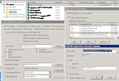
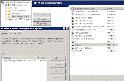
Open Start -> Administrative Tools > Internet Information Services (IIS) Manager. Click "Web Service Extensions" and add a new web service 'C:\Python25\python.exe -u "%s" "%s"'.


3. Configure Website to Enable Python


Go to website that you want to eanble Phyton. Right click the website and go to Properties > Home Directory > Configurations > Mappings. Add a new script mapping ".py" with 'C:\Python25\python.exe -u "%s" "%s"'.

4. Test Python


Write a test file test.py and test it out. Everything should work now.

print
        print 'Status: 200 OK'
        print 'Content-type: text/html'
        print
        print ''
        print '

This is a header

' print '' #this is a comment print 'See this is just like most other HTML' print ' ' print ''
 

5. Configure Control Panel (Optional)


If you have a control panel for your server, you may need to configure it as well. Below is a sample for Helm control panel.


Tuesday, February 15, 2011

Use policy to control bluecoat ProxySG administrator access

 If you would like to control administrator access to the ProxySG Management Console and CLI, you can create policy to configure administrator access privileges.

Using policy rules, you can require administrators to identify themselves by entering a username and password and specify whether read-only or read-write access is given. You can make this policy contingent on IP address, user name, group membership (if credentials were required), and many other conditions.

This solution assumes you have already configured users and groups for authentication (using RADIUS, LDAP, Microsoft Active Directory, or other authentication servers) and created a realm on the ProxySG to connect to these servers.

Procedure to follow

To create policy for ProxySG administrator access:

1. Launch the Visual Policy Manager.
2. Create an Admin Authentication layer (Policy > Add Admin Authentication Layer ).
3. In the Admin Authentication layer, specify the authentication realm that will be used to authenticate administrative users of the ProxySG:
* Right-click in the Action column and choose Set.
* Select New > Authenticate.
* Select the authentication mode and realm. (See ProxySG Authentication Modes.)
* Close the dialogs.
4. Create an Admin Access layer (Policy > Add Admin Access Layer).
5. In the Admin Access layer, define who is allowed to access the ProxySG:

* Right-click in the Source column and choose Set.
* Select New.
* Select the entity (for example, Client IP address/subnet, User, Group) and configure the specifics.
* Close the dialogs.

6. Specify the type of administrator read/write access:

* Right-click the Action column and select Allow Read-only Access or Allow Read/Write Access.

7. By default, the policy applies to any service (HTTP/HTTPS in the Management Console and SSL in the CLI). If you want to control access to just the MC or just the CLI:

* Right-click in the Service column and choose Set.
* Select New > Service Name.
* Select the service you want the rule to apply to (HTTP-Console, HTTPS-Console, or SSH-Console).
* Close the dialogs.
8. Install the policy.

Monday, February 14, 2011

setup DHCP Server and Dynamic DNS with BIND in Debian

This will explain Howto setup DHCP Server and Dynamic DNS with BIND in Debian.

Preparing you system

First you need to install DHCP,BIND servers using the following command

#aptitude install dhcp3-server bind9

This will complete the installation.

This is the network configuration of our DHCP/DNS server we are using for our tutorial
Hostname : router.static.example.org
WAN interface (eth0) : 192.168.99.254 mask 255.255.255.0
LAN interface (eth1) : 172.30.200.254 mask 255.255.0.0
Default gateway : 192.168.99.1

First, we need to tell the DHCP server to only run on eth1 you need to edit the /etc/default/dhcp3-server file using the following command

#vi /etc/default/dhcp3-server

enter the following line save and exit file.

INTERFACES="eth1"

Configuring DHCP Server Configuration

/etc/dhcp3/dhcpd.conf :

This is the DHCP server configuration.

When a computer requests network information from the DHCP server, the DHCP will update the DNS zones

- dyn.example.org : the zone that will map hostnames to IP address
- 201.30.172.in-addr.arpa : the zone in charge of reverse lookups

ddns-domainname is the domain name that the DHCP server will try to update in the zone. For example if my computer is named mycomputer, it will try to upload the dyn.example.org zone with mycomputer.dyn.example.org.

That option is absolutely needed if you have several domains in the “option domain-name” field (the “search” domains that will be in /etc/resolv.conf), or it could try to add the hostname mycomputer.static.example.org to the dyn.example.org zone.

If you only have one domain in the “option domain-name” field, you can go without ddns-domainname as it will upload the zone with the domain specified there.

ddns-update-style interim;
include "/etc/bind/rndc.key";

zone dyn.example.org. {
primary 127.0.0.1;
key "rndc-key";
}

ddns-domainname "dyn.example.org";
option domain-name "static.example.org dyn.example.org";
option domain-name-servers 172.30.200.254;
option routers 172.30.200.254;
option broadcast-address 172.30.255.255;
option ntp-servers 172.30.200.254;

default-lease-time 86400;
max-lease-time 86400;

authoritative;

log-facility local7;

subnet 172.30.0.0 netmask 255.255.0.0 {

range 172.30.201.10 172.30.201.200;

# DNS zones to update
zone 201.30.172.in-addr.arpa. {
primary 172.30.200.254;
key "rndc-key";
}

zone dyn.example.org. {
primary 172.30.200.254;
key "rndc-key";
}
}

Bind Server Configuration
/etc/bind9/named.conf :

Make sure the file contains the following :

include "/etc/bind/named.conf.local";

You should not change that file, as you will specify your options in two other files.

/etc/bind9/named.conf.options :

Your options.

The zone files will be stored under /var/cache/bind/

The queries for unauthoritative domains will be forwarded to 192.168.99.1. You can put the DNS provided by your ISP there (or put the DNS from opendns.com)

options {
directory "/var/cache/bind";

query-source address * ;

forwarders {
192.168.99.1;
};

recursion yes;

version "REFUSED";

allow-recursion {
127.0.0.1;
192.168.99.0/24;
172.30.0.0/16;
};

allow-query {
127.0.0.1;
192.168.99.0/24;
172.30.0.0/16;
};

};

/etc/bind9/named.conf.local :

This will contain your zone declarations

### options #########

include "/etc/bind/rndc.key";
controls {
inet 127.0.0.1 allow { localhost; } keys { "rndc-key"; };
};

### "static" zones #########

zone "static.example.org" {
type master;
file "db.static.example.org";
};

zone "200.30.172.in-addr.arpa" {
type master;
notify no;
file "db.172.30.200";
};

### dynamic zones (updated by DDNS) #########

zone "dyn.example.org" {
type master;
file "db.dyn.example.org";
allow-update { key "rndc-key"; };
};

zone "201.30.172.in-addr.arpa" {
type master;
notify no;
file "db.172.30.201";
allow-update { key "rndc-key"; };
};

Now let’s focus on DNS zones.

In this example we have several zones :

- static.example.org : static zone (like servers with static IP’s)
- dyn.example.org : dynamic zone, updated by DHCP when a computer gets an IP from it
- 172.30.200 : static zone (servers, etc.), which is not updated by DDNS
- 172.30.201 : dynamic zone, will contain information about machines using DHCP

My advise to split the static zones from the dynamic zones, DDNS has a tendency to mess up the zone files, which make them barely readable and manageable.

/var/cache/bind/db.172.30.200 :

$ORIGIN .
$TTL 86400    ; 1 day
200.30.172.in-addr.arpa    IN SOA    static.example.org. postmaster.example.org. (
200806299  ; serial
28800      ; refresh (8 hours)
7200       ; retry (2 hours)
2419200    ; expire (4 weeks)
86400      ; minimum (1 day)
)
NS    ns.static.example.org.
$ORIGIN 200.30.172.in-addr.arpa.
253            IN PTR    server.static.example.org.
254            IN PTR    router.static.example.org.

/var/cache/bind/db.172.30.201 :

$ORIGIN .
$TTL 86400    ; 1 day
201.30.172.in-addr.arpa    IN SOA    static.example.org. postmaster.example.org. (
200806327  ; serial
28800      ; refresh (8 hours)
7200       ; retry (2 hours)
2419200    ; expire (4 weeks)
86400      ; minimum (1 day)
)
NS    ns.static.example.org.
$ORIGIN 201.30.172.in-addr.arpa.

/var/cache/bind/db.static.example.org :

$ORIGIN .
$TTL 86400    ; 1 day
static.example.org    IN SOA    ns.static.example.org. postmaster.example.org. (
200806327  ; serial
28800      ; refresh (8 hours)
7200       ; retry (2 hours)
2419200    ; expire (4 weeks)
86400      ; minimum (1 day)
)
NS    ns.static.example.org.
A    172.30.200.254
$ORIGIN static.example.org.
server            A    172.30.200.253
router            A    172.30.200.254
ns            A    172.30.200.254

ntp            CNAME    router.static.example.org.
smtp            CNAME    router.static.example.org.

/var/cache/bind/db.dyn.example.org

$ORIGIN .
$TTL 86400    ; 1 day
dyn.example.org        IN SOA    ns.static.example.org. admin.example.org. (
200806341  ; serial
28800      ; refresh (8 hours)
7200       ; retry (2 hours)
2419200    ; expire (4 weeks)
86400      ; minimum (1 day)
)
NS    ns.dyn.example.org.
A    172.30.200.254
$ORIGIN dyn.example.org.

Now, make sure the zones will be writable by the user “bind” and restart the services :

# chown bind. /var/cache/bind/*

# /etc/init.d/bind restart

# /etc/init.d/dhcp3-server restart

On a computer on the network :

As root :

Edit /etc/dhcp3/dhclient.conf and set :
send host-name "mycomputer";

Now request an IP :
# dhclient eth0

Let’s imagine the computer has received the IP 172.30.201.200

You should see on the server’s syslog that the DNS zones have been updated.

- mycomputer.dyn.example.org is now bound to 172.30.201.200
- 172.30.201.200 will return mycomputer.dyn.example.org

From your computer, you should be able to verify the zones have been updated properly :

$ nslookup mycomputer
Server:        172.30.200.254
Address:    172.30.200.254#53

Name:    mycomputer.dyn.example.org
Address: 172.30.201.200

$ nslookup 172.30.201.200
Server:        172.30.200.254
Address:    172.30.200.254#53

200.201.30.172.in-addr.arpa    name = mycomputer.dyn.example.org.

You don’t need to type the whole mycomputer.dyn.example.org thing since it will lookup for either :
- mycomputer.dyn.example.org
- mycomputer.static.example.org if the previous wasn’t found
- mycomputer if the previous two were not found

This actually means that if you lookup www.google.com, it would try to resolve www.google.com.dyn.example.org first, then www.google.com.static.example.org, and finally www.google.com

You can avoid those unnecessary lookups by adding a dot to the end of the hostname you are trying to resolve :

# nslookup www.google.com.

This is the purpose of the search domains in /etc/resolv.conf

Sunday, February 13, 2011

Upgrade Cisco IOS in a Router or a Switch

upgrading IOS on Cisco routers and switches is hightly recommendable because of the following reasons
Patch critical vulnerabilities: Just like any other network device or application, Cisco routers and switches are also prone to security holes. And because routers and switches are critical to network infrastructure, you should plug these security holes as soon as possible.
Incorporate new features: Unless an update is simply a bug fix, every new release of the Cisco IOS includes new features. Upgrading your routers and switches in a timely manner means you’ll have more features to potentially make your job easier.
Stay current: “Staying current” with the latest IOS may sound like a flimsy justification to upgrade, especially when you consider your daily task list. However, when you consider the many different tools that communicate with the router’s IOS, staying current can take on a new importance. For example, if you’re using a SNMP network management tool, it may require your router to run a certain version of the IOS.
Follow this procedure if you want to upgrade cisco IOS
NOTE :- Before doing any upgrades plesae take a complete backup of your cisco device configuration for safer side
Download the Correct version of Cisco IOS for you from here http://www.cisco.com/tacpage/sw-center/index.shtml
Write Unsaved configurations
ciscorouter# write memory
Building configuration…
[OK]
Check space on Flash Memory
ciscorouter# show flash
Make sure you have the space left on your cisco device.
Backup Startup Configuration
Setup a TFTP server in the same IP range as the Cisco device to backup the configs, IOS image and also for later to upload the new IOS image.
testrouter# copy startup-config tftp
Address or name of remote host []? 10.10.10.2
Destination filename [startup-config]?
!!
1278 bytes c opied in 0.100 secs
Backup Current IOS Image
testrouter# copy flash: tftp:
Source filename []? xxxxx-xx-xx.121-x.XB
Address or name of remote host []? 10.10.10.2
Destination filename [xxxxx-xx-xx.121-x.XB]?
Now, Load the new IOS image from the TFTP onto the flash
ciscorouter#copy tftp: flash:
Address or name of remote host []? 10.10.10.2
Source filename []? c3560-ipbasek9-mz.122-40.SE.bin
Destination filename [c3560-ipbasek9-mz.122-40.SE.bin]?
Accessing tftp://10.10.10.2/c3560-ipbasek9-mz.122-40.SE.bin…
Loading c3560-ipbasek9-mz.122-40.SE.bin from 10.10.10.2 (via Vlan1): !!!!!!!!!!!!!!!!!!!!!!!!!!!!!!!!!!!!!!!!!!!!!!!!!!!!!!!!!!!!!!!!!!!!!!!!!!!!!!!!!!!!!!!!!!!
!!!!!!!!!!
[OK - 8295106 bytes]
8295106 bytes copied in 124.571 secs (66589 bytes/sec)
Now you need to make sure you are booting with the correct version of IOS image for this you need to use the following command to set.
testrouter(config)#boot system flash:/c3560-ipbasek9-mz.122-40.SE.bin
Now you need to reload the Cisco Router
testrouter# reload
After rebooting cisco device with the new Cisco IOS image you need to make sure this use the following command
testrouter# sh ver
That’s it now we are using the latest IOS on your cisco device


Saturday, February 12, 2011

Configuring Cisco IOS

Configuring Cisco IOS
   
General Information

Routers come with different memory sets:

    ROM
    Shared RAM
    RAM (routing tables and data structures)
    Flash (IOS)
    NVRAM (Configuration files)

Commands

    To select boot source: boot system flash/rom/filname IP-address
    To erase router configuration: write erase
    To display current configuration: sh conf (from NVRAM) or wri term (from RAM)
    To configure router: conf term (or mem, or net) Remember to type CTRL-Z to leave configuration mode
    To configure interface: 
    int e0
            ip address 10.0.0.1 255.255.255.0
            no shutdown
    To show interface status: sh int e0
    To save configuration: wri mem
    enable password = password is shown in clear text when displaying configuration
    enable secret = password is shown encrypted when displaying configuration
    To set number of virtual terminals and password:
    line vty 0 4
            password access
    To disable name lookup: no ip domain-lookup
    To avoid assigning IP address to ethernet port for P-2-P connection:
    int s0
            ip unnumbered e0
    To configure route: ip route 120.0.0.0 255.255.255.0 150.1.1.1
    When connecting two routers with a cross-over cable, "clockrate 64000" is only needed on the router acting as DCE
    Password Recovery Procedure for the Cisco 2500 router: http://www.cisco.com/warp/public/474/pswdrec_2500.html
    Password Recovery Procedure for the Cisco 1600 router: http://www.cisco.com/warp/public/474/pswdrec_1600.shtml
    Do not use Hyperterminal to connect to Cisco routers through the Console plug
    Configuration register is 0x2102 for Cisco 2500 models, 0x102 for Cisco 1600 models
    To save the flash/NVRAM image on a remote TFTP server: #copy tftp flash
    To download a new IOS image into the router from a remote TFTP server: #copy flash tftp
    To update IOS:
        Install Cisco's TFTP Server
        Copy the new image with extension .bin into the TFTP Server's directory
        Launch the TFTP Server
        Connect to the Cisco router through the Console port, switch to admin mode, and type copy flash tftp. Follow the on-screen instructions to

        Note: under W2K, you might to add an extra ".bin" as file extension in addition to the default .bin extension

        Instead of "copy tftp flash", try "copy tftp: flash"
    To list images availables in flash memory, run "dir"
    To disable source-routing: no ip source-route
    Domain name and DNS server: ip domain-name example.com ip name-server 192.168.55.132 ip name-server 192.168.27.32
    To configure AAA user authentication. aaa new-model aaa authentication login lista tacacs+ enable

ALCs

Note: (CHECK) You cannot remove just one line from an existing ACL instruction, as this removes the entire section from IOS. You must type the entire section to add or remove one instruction.

Note: Watch out for the order of instructions in ACLs, as they are processed from top to bottom, ie."deny ip any any" followed by "allow tcp any any" means that a user will not be able to connect using a TCP-based application since the first line is interpreted first.

    access-list 110 permit tcp 172.16.120.0 0.0.0.255 any eq smtp
    access-list 110 permit tcp 172.16.120.0 0.0.0.255 any eq pop3
    access-list 110 permit tcp 172.16.120.0 0.0.0.255 any eq 110
    access-list 110 permit udp any any eq 137
    access-list 110 permit udp any any eq 138
    access-list 110 permit udp any any eq 139
    access-list 110 permit icmp any any
    access-list 110 deny ip any any!

Logging

IOS debugging messages use the same "facilities" for identification. They are, however, formatted differently than error messages, beginning with a timestamp followed only by the "facility" and the debug message output. IOS error and debug messages follow the Unix syslog severity format (0 emerg to 7 debug). Messages appear in the IOS reporting output action depending on the severity level defined.

The IOS provides four output actions for viewing system event and error data. Console logging is activated by default. In its default configuration, all (severity level 7, debugging) message data is sent to the router's console port (line con0). This approach is similar to Unix, where error and event data is sent to /dev/console or /dev/tty0. To disable console logging, use the configuration mode command . Sending logging data only to the console port may seem odd, since most interaction is done using vty sessions, but the console port can be connected to a terminal server, which buffers the message data or a serial line printer (just like Unix) that can print out event messages. While esoteric, these two methods of data collection were quite acceptable for many years and they are secure from a networking perspective since the data is sent via serial to a locally attached display device (just remember to lock the door).

To view system messages over a vty session (line vty 0 - 4), monitor logging must be configured. To view logging data, the enable exec command is run to activate logging output to the vty. To enable monitor logging, use the configuration command . The monitor logging option is the most practical method for viewing logging events in real time. It is highly recommended that you establish two vty sessions, one for displaying event reporting data, and the other for command execution. Often, when troubleshooting or running a debugging sequence, a large amount of logging data is generated. This obscures the vty with logging output, making command entry quite difficult at times. Once terminal monitoring is enables on a vty, it cannot be disabled (unless the logging monitor service is disabled using the configuration command ).

Local storage of logging messages on the router is also available via buffer logging. Since most routers do not have a hard disk, messages are saved in a DRAM buffer. While buffer logging does not directly affect the router's performance, it does consume memory. However, if your router is short on memory, you may see performance issues with processes that need memory if your logging buffer allocation is too large. To verify your router's memory configuration, use the enable exec command which will provide a variety of operational facts about your router, including the amount of DRAM allocated for packet buffers and the amount allocated for operational processes (i.e., routing tables, CEF tables, etc.) To see if you are having memory allocation issues, use the enable exec command . A reasonable buffer allocation is 64k; the "history" logfile is a rotating one, which overwrites the last log entry when the size limit has been reached. To configure buffered logging use the following configuration commands:

    Godzilla-ABR(config)#logging buffered notice
    Godzilla-ABR(config)#logging buffered 64000
    Godzilla-ABR(config)#logging history size 250

The above configuration sets the buffer size at 64k and sets the history count at 250 messages. To view the buffered logging data, use the exec command . This command performs two functions; it reports on the configuration of the router's various reporting display actions, and outputs the logging buffer history (if buffer logging is configured).

To send system messages to a remote syslog host, ;TRAP logging needs to be configured as a reporting output action. Remote reporting has two big advantages over local reporting.

    History and archiving: Storing logs remotely shifts the burden of storing log output to a device with an actual file system and cheap ample storage. This provides the option to keep large-sized log files and/or the ability to archive and store log files.
    Data Manipulation: Once the log data is on a system with tools that can manipulate it, log data can be used to generate and syndicate some very interesting and valuable reports, as you will see later with the SNMP scanner report script.

Configuring TRAP logging is a four step process:

    Define a syslog host using the configuration command .
    Define the logging severity of the messages to be sent using the configuration command .
    Define the IP address that will be associated as the origin address of the logging messages. This is set using the configuration command .
        The final step defines the syslog "facility" that the messages are sent to on the remote syslog server. Use the configuration command . Here is a trap reporting configuration example that uses the Loopback interface as the report origin address:

        Godzilla-ABR(config)#logging 64.128.20.12
        Godzilla-ABR(config)#logging trap informational
        Godzilla-ABR(config)#logging source-interface Loopback 0
        Godzilla-ABR(config)#logging facility local2


Friday, February 11, 2011

Cisco 3600 Series Routers (with PCMCIA cards) Upgrade Procedure

Cisco 3600 Series Routers (with PCMCIA cards) Upgrade Procedure

    Establish a console session to the router
    Verify the amount of free space on the Flash memory card (PCMCIA slot)
    Verify that the TFTP server has IP connectivity to the router
    Copy the new image into the Flash memory card through the TFTP server
    Set boot statements to load the new image upon startup
    Reboot the router to load the new image
    Verify the upgrade

Step 1: Establish a console session to the router

See Establish a console session to the router for more information.

Note: Once connected to the router through the console port, if you get a ">" or "rommon >" prompt, your router is in ROM monitor (ROMmon) mode. If the router is showing the "router (boot)>" prompt, then the router is in boot mode. See booting problems for steps to handle either of these situations.

Step 2: Verify the amount of free space on the Flash memory card (PCMCIA slot)

At this point, you need to verify that you have enough space in the Flash memory card to copy the new image. If there is not enough memory, you need to delete some files to make enough space. In some situations, if the image is very large, you may need to delete the current image in the Flash memory card.

To determine the amount of free space, and to show files currently located in slot0: or slot1:, issue the dir{device:} command.

    3600#dir slot1:
    Directory of slot1:/

      1  -rw-     2779832    c3640-i-mz.113-11c.bin
      2  -rw-     3748760    c3640-i-mz.120-22.bin

Verify that the name and the file size are correct.

If you find that there is not enough space, you can delete the file. The delete{device:}[filename] command deletes the file.

    3600#delete slot1:
    Delete filename []? c3640-i-mz.113-11c.bin
    Delete slot1:c3640-i-mz.113-11c.bin? [confirm]y

Note: Do not reload or powercycle the router if there is not a valid image in the Flash; this causes the router to boot into rommon or bootmode.

Step 3: Verify that the TFTP server has IP connectivity to the router

The TFTP server must have a network connection to the router and must be able to ping the IP address of the router targeted for a TFTP software upgrade. To achieve this, the router interface and the TFTP server must have:

    an IP address in the same range, or

    a default gateway configured

To verify this, check the IP address of the TFTP server.

Step 4: Copy the new image into the Flash memory card through the TFTP server

Now that you have IP connectivity and can ping between the computer acting as a TFTP server and the router, you can copy the image into the right slot.

Note: Before copying, make sure you have started the TFTP server software on your PC and that you have the filename mentioned in the TFTP server root directory. We recommend that you keep a backup of the router/access server configuration before upgrading. The upgrade itself does not affect the configuration (which is stored in nonvolatile RAM -NVRAM). However, this may happen if the right steps are not followed properly.

For RCP applications, substitute RCP for every occurrence of TFTP. For example, use the copy rcp {device:} command instead of the copy tftp {device:} command.

If necessary, you can copy an image from one device to another.

    3600#copy tftp: slot1:
    Address or name of remote host []? 171.68.173.10
    Source filename []? c3640-i-mz.122-7b.bin
    Destination filename [c3640-i-mz.122-7b.bin]?
    Accessing tftp://171.68.173.10/c3640-i-mz.122-7b.bin...
    Erase slot1: before copying? [confirm]n !--- Here you are specifying "n"
                               !--- because there is enough memory available.
    Loading c3640-i-mz.122-7b.bin from 171.68.173.10 (via Ethernet1/0):
    !!!!!!!!!!!!!!!!!!!!!!!!!!!!!!!!!!!!!!!!!!!!!!!!!!!!!!!!!!!!!!!!!!!!!!!!!
    !!!!!!!!!!!!!!!!!!!!!!!!!!!!!!!!!!!!!!!!!!!!!!!!!!!!!!!!!!!!!!!!!!!!!!!!!
    !!!!!!!!!!!!!!!!!!!!!!!!!!!!!!!!!!!!!!!!!!!!!!!!!!!!!!!!!!!!!!!!!!!!!!!!!
    !!!!!!!!!!!!!!!!!!!!!!!!!!!!!!!!!!!!!!!!!!!!!!!!!!!!!!!!!!!!!!!!!!!!!!!!!
    !!!!!!!!!!!!!!!!!!!!!!!!!!!!!!!!!!!!!!!!!!!!!!!!!!!!!!!!!!!!!!!!!!!!!!!!!
    !!!!!!!!!!!!!!!!!!!!!!!!!!!!!!!!!!!!!!!!!!!!!!!!!!!!!!!!!!!!!!!!!!!!!!!!!
    !!!!!!!!!!!!!!!!!!!!!!!!!!!!!!!!!!!!!!!!!!!!!!!!!!!!!!!!!!!!!!!!!!!!!!!!!
    !!!!!!!!!
    [OK - 5996844/11993088 bytes]

    Verifying checksum...  OK (0x13F0)
    5996844 bytes copied in 67.708 secs (89505 bytes/sec)
    3600#

Use the dir slot1: command to check whether the image has been copied to slot1. Below, you can see that the new image c3640-i-mz.122-7b.bin has been copied on the PCMCIA slot1:

    3600#dir slot1:
    Directory of slot1:/

      2  -rw-     3748760    c3640-i-mz.120-22.bin
      3  -rw-     5996844    c3640-i-mz.122-7b.bin

Step 5: Set boot statements to load the new image upon startup

After copying the image through TFTP, you may need to tell the router which image to load upon boot up.

Checking Current Boot Statements

At this point, the new image is now in the slot1. You need to set the router to boot the new image. By default, the router boots the first available image (the default is enabled when there are no boot statements in the configuration).

    3600#show running-config
    Building configuration...

    Current configuration:
    !
    version 12.0
    service timestamps debug uptime
    service timestamps log uptime
    no service password-encryption
    !
    hostname 3600
    !
    boot system flash slot1:c3640-i-mz.120-22.bin
    !
    ip subnet-zero
    !

The commands appear at the begginning of the configuration. In our example above, it shows the router has a boot system command configured as boot system flash slot1:c3640-i-mz.120-22.bin.

If you have boot system command entries in your configuration, you need to remove them from the configuration. For more information on removing boot entries, refer to the next section.

Removing Previous Boot Statements

To remove the commands, enter into configuration terminal mode. From the configuration mode, you can negate any command by typing "no" in front of each boot statement. The following example illustrates the removal of an existing boot statement.

    3600#configure terminal
    Enter configuration commands, one per line.  End with CNTL/Z.
    3600(config)#no boot system flash slot1:c3640-i-mz.120-22.bin
    3600(config)#^Z
    3600#

The statement "no boot system flash slot1:c3640-i-mz.120-22.bin" is removed from the configuration. Verify that the command has been removed by issuing the show running-config command.

Setting New Boot Statements

Now set the router to boot the new image. Issue the following command to set the boot system parameter:

    boot system flash slot#:{imagename} (imagename = name of the new Cisco IOS software image)

    3600#configure terminal
    Enter configuration commands, one per line.  End with CNTL/Z.
    3600(config)#boot system flash slot1:c3640-i-mz.122-7b.bin
    3600(config)#^Z
    3600#write memory
    3d01h: %SYS-5-CONFIG_I: Configured from console by vty0
    Building configuration...
    3600#

Be sure to verify that you are using config-register 0x2102 by issuing the show version command. If it is set up differently, you can change it by issuing the following command in configuration mode:

    3600#configure terminal
    Enter configuration commands, one per line.  End with CNTL/Z.
    3600(config)#config-register 0x2102
    3600(config)#^Z

After changing the config-register, the change takes place at the next reload.

Step 6: Reboot the router to load the new image

For the router to run the new Cisco IOS software image, you need to reload the router. Make sure you have saved the configuration by issuing the copy running-config starting-config or write memory commands.

    3600#write memory
    3d01h: %SYS-5-CONFIG_I: Configured from console by vty0 (127.0.0.11)
    Building configuration...
    3600#reload

Step 7: Verify the upgrade

After the router comes up, make sure you are currently running the new version of code, by issuing the show version command.

    3640#show version
    Cisco Internetwork Operating System Software
    IOS (tm) 3600 Software (C3640-I-M), Version 12.2(7b), RELEASE SOFTWARE (fc1)
    Copyright (c) 1986-2002 by cisco Systems, Inc.
    Compiled Mon 04-Mar-02 20:23 by pwade
    Image text-base: 0x600089A8, data-base: 0x60A6A000

    ROM: System Bootstrap, Version 11.1(19)AA, EARLY DEPLOYMENT RELEASE SOFTWARE (f)

    Router uptime is 2 minutes
    System returned to ROM by reload
    System image file is "slot1:c3640-i-mz.122-7b.bin"

    cisco 3640 (R4700) processor (revision 0x00) with 59392K/6144K bytes of memory.

    Processor board ID 10524422
    R4700 CPU at 100Mhz, Implementation 33, Rev 1.0
    Bridging software.
    X.25 software, Version 3.0.0.
    4 Ethernet/IEEE 802.3 interface(s)
    DRAM configuration is 64 bits wide with parity disabled.
    125K bytes of non-volatile configuration memory.
    4096K bytes of processor board System flash (Read/Write)
    20480K bytes of processor board PCMCIA Slot0 flash (Read/Write)
    20480K bytes of processor board PCMCIA Slot1 flash (Read/Write)

    Configuration register is 0x2102

Verify that the version 12.2(7b) is correct and the config-register is set to 0x2102.
 Page last updated on: 05/19/2007 09:53:42
 All contents are Copyright © 1992–2007 Cisco Systems, Inc. All rights reserved. 


Thursday, February 10, 2011

CISCO IOS Software Installation and Upgrade Procedure

 OS Software Installation and Upgrade Procedure

This procedure applies to the following Cisco products:

    Cisco 10001
    Cisco 14001
    Cisco 1600-R
    Cisco 1700
    Cisco 2600
    Cisco 3600
    Cisco 3700
    Cisco 4000
    Cisco 4500
    Cisco 4700
    Cisco AS53001
    Cisco MC3810
Introduction

This document explains the procedure for upgrading a Cisco IOS® Software image on Access router platforms. The examples provided from the 2600 and 3600 Series Routers also apply to the list of router platforms mentioned below. The Cisco IOS software file names may vary depending on the Cisco IOS software version, feature set, and platform.The following Cisco series routers are addressed in this document:

    Cisco 1000 Series Routers
    Cisco 1400Series Routers
    Cisco 1600-R Series Routers
    Cisco 1700 Series Routers
    Cisco 2600 Series Routers
    Cisco 3600 Series Routers
    Cisco 3700 Series Routers
    Cisco 4000 Series Routers
    Cisco 4700 Series Routers
    Cisco AS5300 Series Routers
    Cisco MC3810 Series Routers

The information in this document is based on Cisco IOS Software Release 12.0 or later.

The Field Engineer must receive permission from Cisco VISE that a software image upgrade is required, BEFORE carrying out any of these procedures.
Before You Begin

Step 1: Install a TFTP Server
A Trival File Transfer Protocol (TFTP) server or a Remote Copy Protocol (RCP) server application must be installed on a TCP/IP-ready workstation or PC. Once the application is installed, a minimal level of configuration must be performed.

    Note: Cisco no longer supply or support their own TFTP Server application, however searching within your favourite search engine for "TFTP Server" will locate a third party TFTP application for you. Alternatively, you may find Cisco's unsupported TFTP Server application on the COMPASS CD.

    First, the TFTP application must be configured to operate as a TFTP server as opposed to a TFTP client.

    The outbound file directory must be specified. This is the directory in which the Cisco IOS Software images are stored. Most TFTP applications provide a set-up routine to assist in these configuration tasks.

Step 2: Request which IOS Software Image is to be used.
The Field Engineer must ask the VISE engineer or the customer, which image is to be upgraded. It is not the responsibility of the Field Engineer to recommend software image versions. The software image may be provided by the customer, and so the Field Engineer must ask the Cisco VISE engineer for directions.

Step 3: Download the Cisco IOS Software Image
Download the Cisco IOS Software image into your workstation or PC from the Cisco website (http://www.cisco.com).
Software Installation and Upgrade Procedures

    Routers with Internal Flash (for example, 2600 Series Routers)
    Routers with PCMCIA Flash cards (for example, 3600 Series Routers)

Cisco 2600 Series Routers Upgrade Procedure

    Establish a console session to the router
    Verify that the TFTP server has IP connectivity to the router
    Copy the new image into the Flash memory of the 2600 Series Router through the TFTP server

Step 1: Establish a console session to the router

Even if it is possible to connect to the router through a telnet session, it is strongly recommended to be directly connected to the router using the console port. The reason is that if something goes wrong during the upgrade, it might be necessary to be physically located next to the router to power-cycle it. Moreover, the telnet connection will be lost while the router is rebooting during the upgrade procedure.

A rolled cable (usually a flat black cable) is used to connect the console port of the router to one of the COM ports of the PC.

Once the PC is connected to the console port of the router, you need to open Hyperterminal on the PC, and use the following settings:

         Speed 9600 bits per second

         8 databits

         0 parity bits

         1 stop bit

         No Flow Control

Note: If you are getting any garbage characters in the hyperterminal session, this means that you have not set the hyperterminal properties properly, or the config-register of the router is set to a non-standard value for which the console connection speed is higher than 9600 bps.  Check the value of the config-register using the show version command (shown in the last line of the output) and ensure it is set to 0x2102 or 0x102. It is necessary to reload the router for a configuration register change to take effect. Once you are sure the console speed is set to 9600 bps on the router side, you should check the hyperterminal properties as above .

Booting Problems

Once you are connected to the console port of the router, you might notice that the router is either in ROMmon or Boot mode. These two modes are used for recovery and/or diagnostic procedures. If you do not see the usual router prompt, you should follow the recommendations below to proceed with the upgrade procedure installation.

    Router boots in rommon mode, and the following message appears when you issue dir flash: command.

        rommon 1 > dir flash:
        device does not contain a valid magic number
        dir: cannot open device "flash:"
        rommon 2 >

    When you see the above error message, it means the Flash is empty or the filesystem is corrupted. A Xmodem console download procedure using ROMmon may then be necessary.
    Router boots in boot mode, with the following messages on the console:

        router(boot)>
        device does not contain a valid magic number
        boot: cannot open "flash:"
        boot: cannot determine first file name on device "flash:"

    When you get the above error messages on the console output, it means the Flash is empty or the file system is corrupted. Copy a valid image on the Flash by following the procedures provided in this document.

Step 2: Verify that the TFTP server has IP connectivity to the router

The TFTP server must have a network connection to the router, and must be able to ping the IP address of the router targeted for a TFTP software upgrade. To achieve this, the router interface and the TFTP server must have:

        an IP address in the same range, or

        a default gateway configured.

To verify this, check the IP address of the TFTP server.
Step 3: Copy the new image into the Flash memory of the 2600 Series Router through the TFTP server

    Now that you have IP connectivity and can ping between the computer acting as a TFTP server and the router, you can copy the Cisco IOS Software image into the Flash.

    Note: Before copying, make sure you have started the TFTP server software on your PC and that you have the filename mentioned in the TFTP server root directory. We recommend that you keep a backup of the router/access server configuration before upgrading. The upgrade itself does not affect the configuration (which is stored in nonvolatile RAM (NVRAM). However, this might happen if the right steps are not followed properly.

    For RCP applications, substitute RCP for every occurrence of TFTP. For example, use the copy rcp flash command instead of the copy tftp flash command.

        2600> enable
        Password:xxxxx
        2600#
        2600# copy tftp flash

    If necessary, you can copy an image from one device to another.
    Specify the IP address of the TFTP server.

    When prompted, enter the IP address of the TFTP server as in the following example:

        Address or name of remote host []? 10.10.10.2

    Specify the filename of the new Cisco IOS Software image.

    When prompted, enter the filename of the Cisco IOS Software image to be installed, as in the following example:

        Source filename []? c2600-i-mz.121-14.bin

    Note: The filename is case sensitive, so be sure to enter it correctly.
    Specify the destination filename.

    This is the name the new software image will have when it is loaded onto the router. The image can be named anything, but common practice is to enter the same image filename.

        Destination filename []? c2600-i-mz.121-14.bin

    Note: If you see the below error message:

    %Error copying tftp://10.10.10.2/c2600-i-mz.121-14.bin
    (Not enough space on device) 

    This indicates that there is not enough room available in Flash to copy the image. You need to erase a file(s) before copying the new image from the TFTP server.
    Upgrade the new image from a TFTP server

    2610#copy tftp flash
    Address or name of remote host []? 10.10.10.2
    Source filename []? c2600-i-mz.121-14.bin
    Destination filename [c2600-i-mz.121-14.bin]?y
    Accessing tftp://10.10.10.2/c2600-i-mz.121-14.bin...
    Erase flash: before copying? [confirm]y !---If there is not enough
                                     !--- memory available, erase the Flash
    Erasing the flash filesystem will remove all files! Continue? [confirm]y
    Erasing device... eeeeeeeeeeeeeeeeeeeeeeeeeeeeeeeeeeeeeeeeeeeeeeeeeeeeee
    eeeeeeeeee ...erased
    Erase of flash: complete
    Loading c2600-i-mz.121-14.bin from 10.10.10.2 (via Ethernet0/0): !!!!!!!!
    !!!!!!!!!!!!!!!!!!!!!!!!!!!!!!!!!!!!!!!!!!!!!!!!!!!!!!!!!!!!!!!!!!!!!!!!!
    !!!!!!!!!!!!!!!!!!!!!!!!!!!!!!!!!!!!!!!!!!!!!!!!!!!!!!!!!!!!!!!!!!!!!!!!!
    !!!!!!!!!!!!!!!!!!!!!!!!!!!!!!!!!!!!!!!!!!!!!!!!!!!!!!!!!!!!!!!!!!!!!!!!!
    !!!!!!!!!!!!!!!!!!!!!!!!!!!!!!!!!!!!!!!!!!!!!!!!!!!!!!!!!!!!!!!!!!!!!!!!!
    !!!!!!!!!!!!!!!!!!!!!!!!!!!!!!!!!!!!!!!!!!!!!!!!!!!!!!!!!!!!!!!!!!!!!!!!!
    !!!!!!!!!!!!!!!!!!!!!!!!!!!!!!!!!!!!!!!!!!!!!!!!!!!!!!!!!!!!!!!!!!!!!!!!!
    !!!!!!!!!!!!!!!!!!!!!!!!!!!!!!!!!!!!!!!!!!!!!!!!!!!!!!!!!!!!!!!!!!!!!!!!!
    !!!!!!!!!!!!!!!!!!!!!!!!!!!!!!!!!!!!!!!!!!!!!!!!!!!!!!!!!!!!!!!!!!!!!!!!!
    !!!!!!!!!!!!!!!!!!!!!!!!!!!!!!!!!!!!!!!!!!!!!!!!!!!!!!!!!!!!!!!!!!!!!!!!!
    !!!!!!!!!!!!!!!!!!!!!!!!!!!!!!!!!!!!!!!!!!!!!!!!!!!!!!!!!!!!!!!!!!!!!!!!!
    !!!!!!!!!!!!!!!!!!!!!!!!!!!!!!!!!!!!!!!!!!!!!!!!!!!!!!!!!!!!!!!!!!!!!!!!!
    !!!!!!!!!!!!!!!!!!!!!!!!!!!!!!!!!!!!!!!!!!!!!!!!!!!!!!!!!!!!!!!!!!!!!
    [OK - 4501480/9001984 bytes]

    Verifying checksum...  OK (0xAC8A)
    4501480 bytes copied in 56.88 secs (80383 bytes/sec)

    The copying process takes several minutes; the time differs from network to network. During the copy process, messages are displayed to indicate which file has been accessed.

    The exclamation point "!" indicates that the copy process is taking place. Each exclamation point indicates that ten packets have been transferred successfully. A checksum verification of the image occurs after the image is written to Flash memory.

After you have upgraded the Flash, you need to reload the router using the reload command.

Before you reload the router, you need to check two things:

    The value of the config-register - You can check this using the show version command. The value is shown in the last line of the show version output. It should be set to 0x2102.

        2610#configure terminal
        Enter configuration commands, one per line.  End with CNTL/Z.
        2610(config)#config-register 0x2102
        2610(config)#^Z

    The other files on the Flash - If the first file in the Flash is not the Cisco IOS Software image, but a configuration file or something else, then you need to configure a boot system statement in order to boot the specified image. Otherwise, the router will try to boot with the configuration file or the first file in the Flash; this will not work. If there is only one file in the Flash which is the Cisco IOS Software image, then this step is not necessary.

        2610#configure terminal
        Enter configuration commands, one per line.  End with CNTL/Z.
        2610(config)#no boot system
        2610(config)#boot system flash c2600-i-mz.121-14.bin
        2610(config)#^Z

Note: If you type the reload command, the router asks you if you want to save the configuration. You should be very cautious here. The reason is that if the router is in boot mode for instance, it is a subset of the full Cisco IOS software which is running and there is no routing functionality. Therefore, all the routing configuration is gone in the running configuration and if you save the configuration at this time, then you erase the good startup-configuration in NVRAM and replace it by the incomplete running-configuration. Save the configuration only if you are sure that you have the full configuration in the output of show run. It is NOT necessary to save the configuration to take into account the new config-register if this one has been changed previously. That is done automatically.

    2610#reload
    
    System configuration has been modified. Save? [yes/no]: y
    Building configuration...
    [OK]
    Proceed with reload? [confirm]y

Verify that the router is running with the proper image. After the reload is complete, the router should be running the desired Cisco IOS Software image. Use the show version command to verify.

    2610#show version
    00:22:25: %SYS-5-CONFIG_I: Configured from console by console
    Cisco Internetwork Operating System Software
    IOS (tm) C2600 Software (C2600-I-M), Version 12.1(14), RELEASE SOFTWARE (fc1)
    Copyright (c) 1986-2002 by cisco Systems, Inc.
    Compiled Mon 25-Mar-02 20:33 by kellythw
    Image text-base: 0x80008088, data-base: 0x80828788

    ROM: System Bootstrap, Version 11.3(2)XA4, RELEASE SOFTWARE (fc1)

    2610 uptime is 22 minutes
    System returned to ROM by reload
    System image file is "flash:c2600-i-mz.121-14.bin"